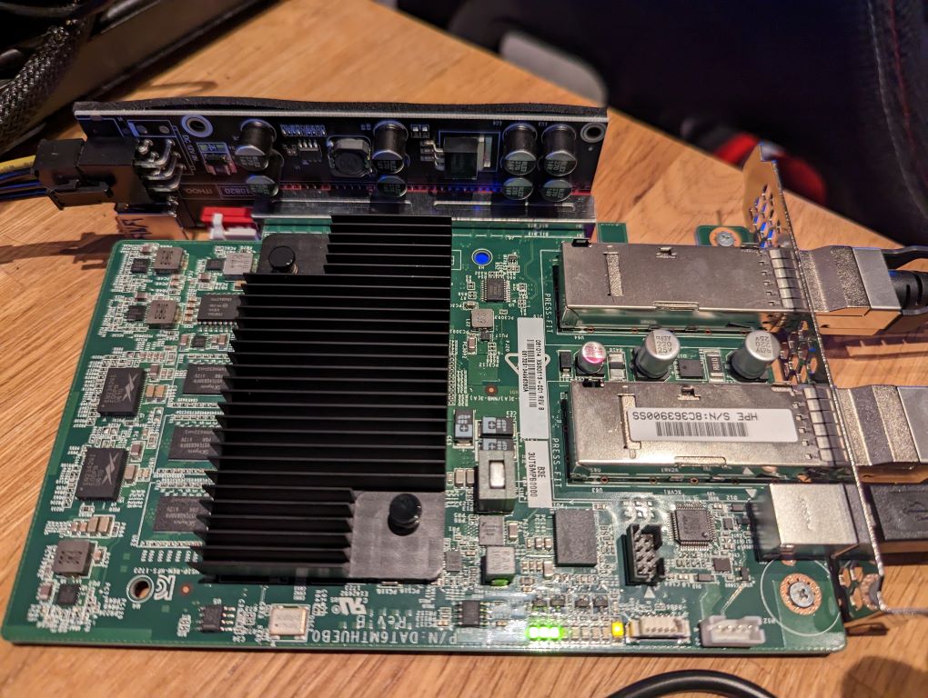
Azure FPGA device
This post describes bringing up the Microsoft Storey Peak board (under Windows).
Software setup
All community work done before on this board was done using the Linux OS. While I do use Linux a lot I have Windows on my desktop machine so I got going with that and installed Quartus Prime Standard edition, as Lite and Pro don’t support this Stratix V part.
Accessing the board
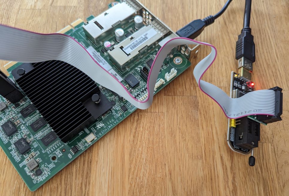
Development kits are typically programmed with an external USB<==>JTAG converter plugged in an on-board JTAG header. The setup of this board is a bit different, with an USB connector on the back feeding into an on-board FTDI 232H chip: an USB bridge chip which can drive multiple protocols such as SPI, I2C, UART and JTAG.
USB drivers
When you plug this in on Windows you get a serial COM port assigned with the default FTDI driver. This is too limiting, and for full access we need something better. Using Zadig we can install WinUSB drivers that unlock the full capabilities in a standardized way.
We can test see if we can access the JTAG over USB using OpenOCD:
TODO prompt.
Finally this can also be used to init the FTDI chip:
openocd -f interface/ftdi/um232h.cfg -c "adapter speed 2000; transport select jtag; jtag newtap auto0 tap -irlen 10 -expected-id 0x029070dd; init; exit;"
Note: make sure to use the standalone openocd, not the one packaged with Quartus.
Quartus JTAG driver
Getting it going in Quartus is the next challenge. Jan Marjanovic wrote a driver for Quartus for this chip. However, that was on Linux and I am stubborn. After a lot of fighting with msys2, ming, gcc etc. I got a tweaked version of Jan’s driver to compile on Windows. Once it did and I understood how it worked, I rewrote it in a Windows native way here.
To get going, follow the instructions: compile the driver and install it in the Quartus bin64 folder. As the original version it doesn’t come with init: after you plug the USB you need to init the JTAG with OpenOCD (see above).
If it does not come online in Quartus Programmer, you need to check 2 things (this took me a few hours):
- open component services and disable the Quartus JTAG server (don’t just stop it, make sure it can’t start anymore).
- open process explorer and kill any jtagserver.exe that may still be running.
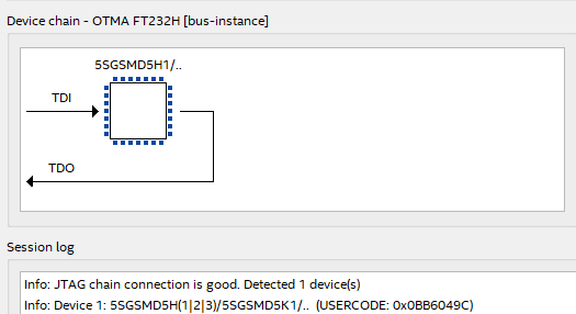
Now you should see the driver coming online, and can see the FPGA chip it controls, meaning we are all set for programming the device through USB<==>JTAG in Quartus.
Bringing up the board
With FPGAs, there are 100s of pins that may lead to anywhere (DDR, PCIe, network, LEDs, EEPROM, Flash, I2C, clock chips, etc.). The device/chip alone isn’t worth anything if you don’t know what is connected where.
A lot of work was done by others to find these pinouts, and it’s all documented in the reference design. Next step is to check out that project and compile it in Quartus.
Custom part and hard ip
The code for the device closest to this part in Quartus is 5SGSMD5K2F40I3L. However, when you first compile the bring-up design you find out it won’t compile as there are 2 hard PCIe IP in the design and this device is only supposed to come with 1 of those. This is where it gets murky. The Stratix V GS chip on this board is actually a custom part ordered by Microsoft containing 2 PCIe hard-ip, and since the custom device part (5SGSKF40I3LNAC) is not in the GUI, we can’t select it there. It may not even be in the general released Quartus software database.
So we need to trick Quartus into allowing us to pick a 2nd PCIe hard-ip. It was found you can do that by overriding a function in the ddb_dev library. On Linux you can quite easily override a library function with LD_PRELOAD. Not so on windows.
My first approach was to inject a dll into the Quartus process and hook/override this particular function but I ran into 2 issues: the first is Windows thinks I wrote a virus (you can suppress this message), but moreover Quartus spawns child processes (quartus_map, quartus_fit, etc.) that need to be hooked as well. My second approach was to write a shim dll in front of dev_ddb that forwards all exports to the original dll except the one function I want to tweak. That worked, you can find the project here, with instructions on how to install it.
Now you will be able to build the reference design.
Intermezzo: saving the factory firmware
Before I burned the design I dumped the factory firmware just to be certain. I did this through Quartus - producing a .jic file - and through direct connection with the ROM using an EEPROM programmer (CH314a) and a test clip.
Programming the design
I took a small risk here. The reference design was for the Storey Peak version of the board, and while the PCIe Pikes Peak version was explored, I wasn’t certain pinouts would be the same. So there was a real chance I would damage the board if I burned the image and pins would not match up. But no smoke came out after burning, so finally we were set to interact with the board.
Testing the board devices using the soft CPU
The reference design contains a soft CPU - a CPU defined in FPGA logic - that’s connected to all the board peripherals. The soft CPU - in this case a Nios II 32 bit RISC CPU - is running after programming the board, but doesn’t have any software to execute yet.
The reference design comes with an app to run on the CPU. This app will run on the bare metal (in as far as you can say that on a soft CPU): there is no BIOS or OS. The app is the only thing that runs here.
Install toolchain
To get software on the soft CPU you need the Nios II Software Build tools for Eclipse accessible from the Tools menu in Quartus. Except that’s just a link to nowhere initially, you first need to install this special version of Eclipse.
Compiling the code
After installation, run Nios 2 - Eclipse, set the workspace to the software/ folder in the bringup repo, and import the projects in this same folder (make sure to import them as Nios 2 projects, not regular C++ ones).
You should now see a otma_bringup project (the user code), and a otma_bringup_bsp project (the Board Support Package, defining the external peripherals, generated from the socpinfo file which came out of the Quartus compile).
Depending on the version of Quartus you are on, you may need to change the BspVersion value in the bsp project settings file. Also, make sure to update the path to the SopcDesignFile if needed. Afterwards, generate the BSP from the Nios 2 context menu. This should fixup the bsp project.
Next you want to try compile everything. Your luck may vary and I think this is by far one of the worst toolchains I ever used. You may need to include the ip_cores sources. In the end I just copied everything in there to the otma_bringup project, as nothing else seemed to work.
Running the code
If everything worked - fingers crossed - you are now interacting with the code running on the soft CPU. You can test the various peripherals from here.
Next steps
Coming from a professional developer background, some of the steps above felt suboptimal. For testing initial board bring-up Nios ii was ok, but what would be the process to load a full fledged BIOS and OS on the soft CPU? How do we reproducibly generate the design for the FPGA without clicking through GUIs?
Designs as code - LiteX
I wanted my next design to be more streamlined and not depend on this flaky toolchain (Eclipse integration with Nios), so I explored open source softCPU and SoC building pipelines. One great find was LiteX, which allows you to generate designs from the command line with or without a CPU including base components like DRAM, PCIe, SDCard, Leds, you name it.
LiteX is designed to run on Linux, but it works fine on Windows with WSL.
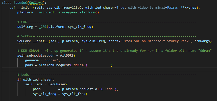
Every LiteX board requires a platform file (for pin mappings etc.) and a target file (that specifies the SoC architecture, such as CPU, memory, peripherals plus how they are connected). It seems I was the first to run LiteX with this board, so I created a board definition (TODO: send a pull request).
Note: if you find the error that quartus isn’t on your path you’re good. You may call out from WSL to windows by defining symlinks to the quartus.exe executables, but I just modified the output .sh to .bat and ran that in Windows next.
Finally we have a design build and ready to be streamed to the FPGA
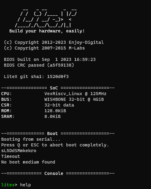
Caveats:
- I did not yet manage to connect the Altera UniPHY DDR3 controller (with Avalon-MM bus) to the Wishbone bus - without the Soft CPU deadlocking. So the DDR3 is technically working but not accessible by the CPU.
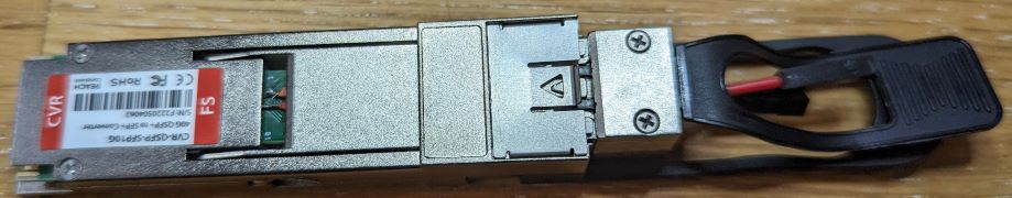
- to get UART output (there are no GPIO pins on this board), I wired UART over the I2C pins of a QSFP port (by re-soldering a SFP28 module and fitting that in a QSFP+ adapter):