
Fixing by breaking
Most people in infrastructure I know have some equipment to play around with, also known as a ’lab environment’. My personal lab is running 24/7 in the closet of my home office. I use it to periodically test new releases of virtualization and container software from the likes of Pivotal and VMware. However, a machine running 24/7 and using ~150 Watts when idling is a bit of a waste. The one thing preventing me from switching it off was a virtualized NAS (running a ZFS pool) which I also use to expose fileshares to the rest of the home. So that had to keep running.
I made a plan to move the NAS VM to another less energy hungry machine. That machine would be my existing desktop pc containing an Intel 4670K, which would when undervolted be an ideal host for the NAS and vCenter. So I started by replacing the CPU cooler with a Noctua to make it run silent (I accidentally ordered the massive 14cm instead of the 12cm one which almost didn’t fit over the RAM), and moved the drives over:
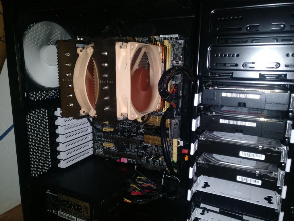 Build with the Noctua NH-D14
Time to turn it on: immediate power down again…something was wrong. I unplugged the 2 drives that were on the last cable I plugged and it would start. Plug them again and it would power off. It must be something was shorting in the HDDs, but how?
I use modular power supplies in all my builds as it keeps the build as clean as possible. So when moving the drives, I unplugged the SATA power cable and moved that over to the new case as well as they use the same connectors. Ideal right?
Well, there’s no discernable difference except the pinout is different…which is evil as the physical contract (connector) implies something about the electrical contract (the pinout): if it physically fits, electronically it should be fine as well. I measured the voltages and discovered 12V must have been applied to the 5V SATA input, and 5V to one of the grounds….oops. My immediate next step was to check with the ‘correct’ modular cable whether the drives would still spin up, but no luck. Something was fried.
Now I have backups of my really important documents in other places as well, but these two mirrored drives breaking at the same time was a nuisance. They kept things like my Steam library and most VMs for my lab, and it would be lots of work to get that back. I couldn’t stand it and started to investigate what happened, perhaps it was fixable after all.
The first thing I did was (after googling) unscrewing the PCB of one of these things, and turning it over:
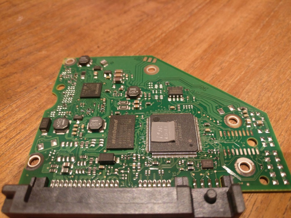 PCB of a Seagate 2TB desktop drive. The SATA connector pins are visible on the bottom.
So nothing was obviously wrong or burned here..which was good and bad. Good because not the whole PCB was fried, bad because I still didn’t know what was. The one thing I did notice is that this SMD stuff is INSANELY tiny, if it came to modifications I would never be able to do much. I hoped this wasn’t necessary.
My hope was quickly quenched as I searched for replacement PCBs online. It appears even if you find a replacement PCB of the exact version your drive needs (my two identical size drives from the same vendor series had wildly different PCBs), there’s a BIOS chip on each of these PCBs that’s unique to the drive, and you have to transplant that to the replacement PCB to get access to the drive again. I didn’t have the tools for doing it myself or the patience to ship my PCB and have all of that done.
More googling awaited, and I learned the inputs on these PCBs typically come with protective circuitry to prevent damage to the controller chips from applying wrong voltages and from Electro Static Discharge (ESD). These protections come in the shape of Transient Voltage Suppression (TVS) diodes. They are designed to safely short huge but brief voltage spikes (ESD) to ground and keep functioning. It turns out they are less capable when you apply constant overvoltages :(
When they blow up they stay in their short state (instead of open), creating a permanent short to ground preventing the drive from ever spinning up again (and making sure the power supply powers down immediately).
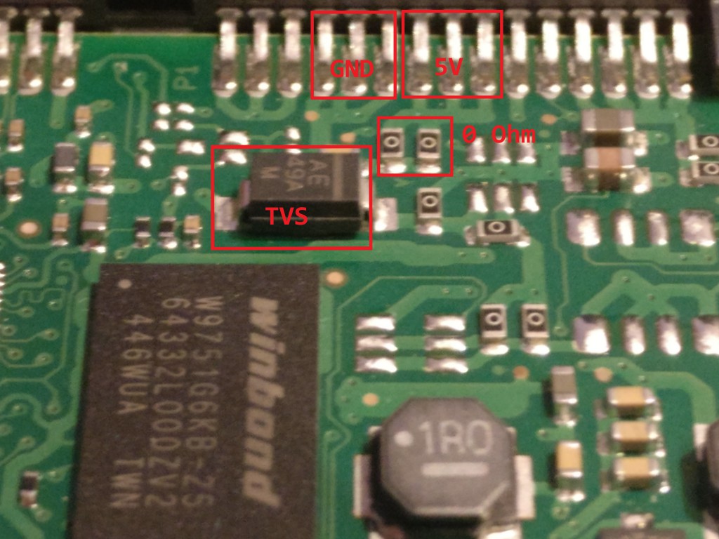 Zoom in of PCB close to the SATA connector. The 5V and GND inputs are highlighted as well as the presumed 5V TVS and microfuses (0 Ohm resistors).
There should be 2 TVS diodes on most PCBs: one for the 5V and one for the 12V input. I searched for images and measured the resistance of both chips I recognized as similar to the ones I found online. One was short-circuited. I confirmed the traces on the PCB connected it to the 5V SATA input and ground which confirmed the hypothesis that 12V was accidentally applied to the 5V input. So this was likely the broken TVS. As everything is so small, not every chip is identifiable, so some educated guessing remains involved here…
So I clipped it, which was the most nerve wrecking thing I did last week.
By clipping it we break the short from 5V to GND. Also it removes all ESD protection for ever, so I better ground myself properly when hooking it up again. Which is what I did next.
And the drive still didn’t work…
This was caused by the second layer of protective circuitry: 0 Ohm resistors or ‘SMD fuses’. When too large currents are sent through these devices, they break which causes their resistance to go up from 0 to ~100 or so Ohms. As you can see in the image, the 2 highlighted ones were all that remained in the path from 5V to GND after the TVS shorted, causing them to fail as well. I confirmed the theory and measured a high resistance across them.
I tried to short them by applying a blob of solder. Did I mention everything is insanely tiny yet? After fumbling with my soldering iron for some time I gave up and examined the PCB some more. I found there was a pad on the PCB connected to the 5V input interrupted by 6 microfuses (2 of whom where broken), and soldered a wire from the 5V input to a pad on the PCB bypassing all of them. All safeties were gone now.
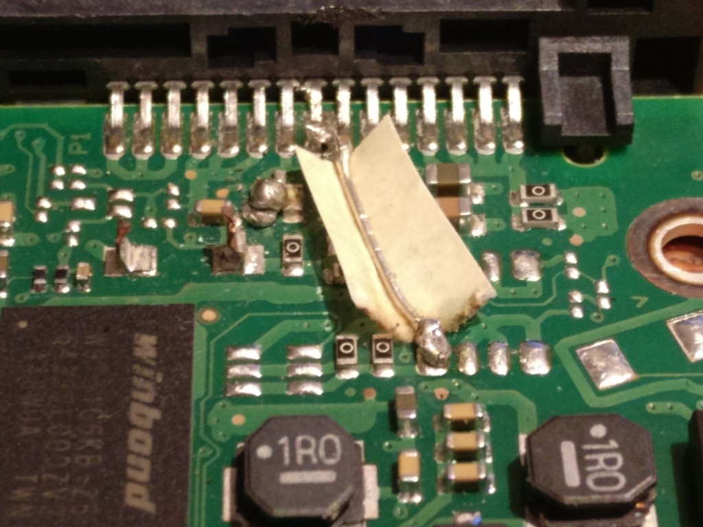 Zoom of the PCB without the clipped TVS, and with a wire bypassing the 0 Ohm resistors.
But it worked :D
I quickly let my ZFS pool resilver with a new disk copying all the data and I was operational again some hours later.
So now I used my old desktop for this thing, I needed a new desktop. More on that later :)